EcoScreen: BR5-36
Commercial & Industrial Products
Specialty

Specialty
Metl-Span, a Nucor® company, is committed to manufacturing and distributing only the highest-quality insulated building metal panel products. We offer specialty products to meet your needs and save you time and money, including EcoScreen, our perforated single skin, and Metl-Vision, our integrated window system.
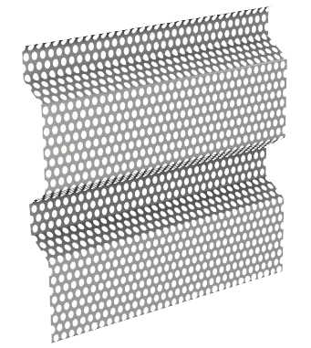
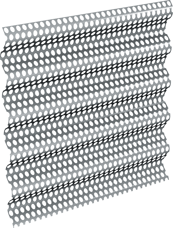
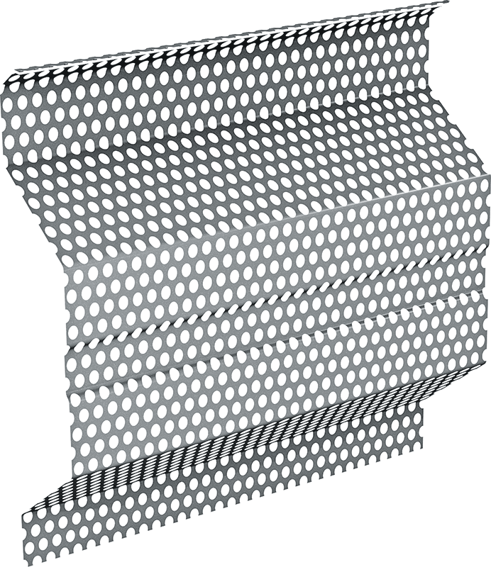
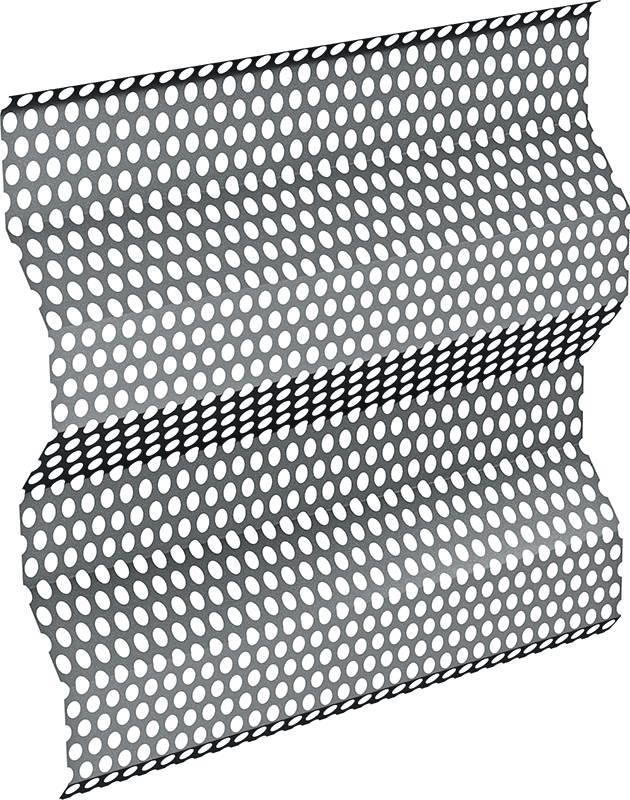
Perforated Wall Panels
EcoScreen Perforated panels combine an airy aesthetic with outstanding performance, blending industrial and other applications with their surroundings. They create a screen wall using either 20-gauge stainless steel or 0.04″ painted aluminum via a unique fabrication process.
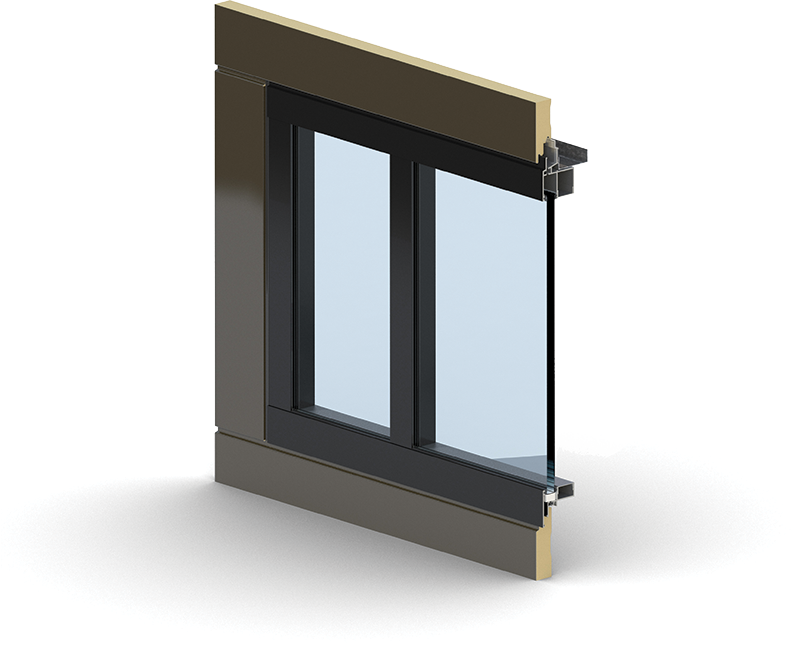
Metl-Vision Window System®
Metl-Span has developed the Metl-Vision® window system to further complement the exceptional architectural aesthetics and function of Metl-Span’s horizontal wall panels.
Have Questions About Our Products?
Please fill out the following information and an experienced sales representative will be in contact. We look forward to hearing from you!
View our Privacy Policy